
svgDOM Features
SVG-files may contain path-elements and are transformed across several group-levels. Reading svg-files in the cad4tcl-package should be that simple and performant as possible. Therefore style and transform attributes should be transformed to its resulting shape. For the use of cad4tcl with tk::canvas all the path elements should be converted into a readable represenatation. Of course this approach is weak in case of clipping objects but gives an opportunity to handle svg-files for the tk::canvas.
convert path elements
SVG-files may contain path-elements but unfortunately the tk::canvas is not able to render native svg-path-elements.
Therefor svgDOM :
- convertes all svg-nodes (oval, rect, path) into polygons and polylines
- if a path-element contains more than one sinlge shape the path-element is splitted into single shapes
- if an oval is detected as circle it is returned as oval and not as polygon
An example svg-file is shown here:
The path-element with the id "path002" contains 2 shapes, where the second shape clips
out a window from the first shape and makes it transparent in the are of the second shape.
                        <?xml version="1.0" encoding="UTF-8" standalone="no"?>

                        <svg id="svg2" xmlns="http://www.w3.org/2000/svg" viewBox="0 0 100 100" version="1.1" >


                            <rect id="rect001" fill="lightgray" stroke="darkgray" stroke-width="0.5"

                                    x="10" y="15" width="30" height="20"/>

                            <path id="path002" fill="lightblue" stroke="darkblue" stroke-width="0.5" fill-rule="evenodd"

                                    d="M 20 18  L 50 15  60 45  20 37 Z

                                       M 30 21  L 43 20  50 40  30 36 Z"/>


                        </svg>
The renderes svg file looks like this:
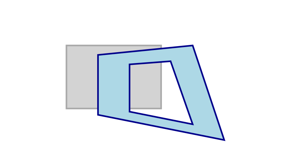
complex path-element rendered in Mozilla Firefox
Depending on your needs (provide svg for tk::canvas or tkpath) you can control the output of svgDOM:
handle path elements for native use in tkpath
$svgObj pathType path
The result of svgDOM for pathType:path will look like this:
                        <?xml version="1.0" encoding="UTF-8"?>

                        <svg xmlns="http://www.w3.org/2000/svg" id="svg2" viewBox="0 0 100 100" version="1.1">

                            <polygon id="rect001" fill="lightgray" stroke="darkgray" stroke-width="0.5"

                                    points="10.0,15.0 40.0,15.0 40.0,35.0 10.0,35.0"/>

                            <path id="path002" fill="lightblue" stroke="darkblue" stroke-width="0.5"

                                    d="M 20.0,18.0 L 50.0,15.0 60.0,45.0 20.0,37.0 Z

                                       M 30.0,21.0 L 43.0,20.0 50.0,40.0 30.0,36.0 Z"/>

                        </svg>
The path-element is still a path element and there were no need to change the point definitions. In the first step we do not care about polygon which represents the rectangle. The rendering of this result will look like this:

There is no difference to the rendering of the original file. (rendering by simplifySVG of package cad4tcl)
handle path elements for limited use in tk::canvas
... this is the default setting for svgDOM
$svgObj pathType fraction
The result of svgDOM for pathType:fraction and its rendering will look like this:
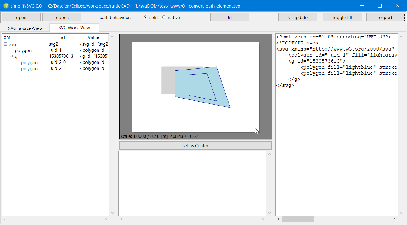
Clipping does not work for tk::canvas. (rendering by simplifySVG of package cad4tcl)
You can see that the clipping of the second shape of the path element does not work.
Instead of this it is shown as a filled shape.
What happend?
lets see the resulting xml:
                        <svg xmlns="http://www.w3.org/2000/svg" id="svg2" viewBox="0 0 100 100" version="1.1">

                            <polygon id="rect001" fill="lightgray" stroke="darkgray" stroke-width="0.5"

                                    points="10.0,15.0 40.0,15.0 40.0,35.0 10.0,35.0"/>

                            <g id="path002">

                                <polygon fill="lightblue" stroke="darkblue" stroke-width="0.5"

                                    points="20.0,18.0 50.0,15.0 60.0,45.0 20.0,37.0" id="path002_0"/>

                                <polygon fill="lightblue" stroke="darkblue" stroke-width="0.5"

                                    points="30.0,21.0 43.0,20.0 50.0,40.0 30.0,36.0" id="path002_1"/>

                            </g>

                        </svg>
The path-element is not a path-element anymore. This is, because tk::canvas will not be able to render path-elements. In this case the path-element is replaced by a group-node with the id "path002" and the two shapes were converted into two single shapes with the ids "path002_0" and "path002_1"
combine transform attributes
The following example shows a svg-rectangle that is defined by
- x="10"
- y="15"
- width="30"
- height="20"
and is repositioned by different group-nodes:
- translate(50,20)
- scale(2)
- rotate(45)
- translate(5,10)
This svg-file is shown here:
                        <?xml version="1.0" encoding="UTF-8" standalone="no"?>

                        <svg id="svg2" xmlns="http://www.w3.org/2000/svg" viewBox="0 0 150 150" version="1.1">

                            <g transform="translate(50,20)">

                                <g transform="scale(2)">

                                    <g transform="rotate(45)">

                                        <g transform="translate(5,10)">

                                            <rect x="10" y="15" width="30" height="20"

                                                    fill="yellow" stroke="blue" stroke-width="1"/>

                                        </g>

                                    </g>

                                </g>

                            </g>

                        </svg>
svgDOM parses the given file and returns a converted svg-file, where all the given transformation are combined and at least represented in the shape definition of the resulting rectangle that is represented as a polygon here. All the group nodes does not have any transform-attribute anymore.
                        <?xml version="1.0" encoding="UTF-8"?>

                        <svg xmlns="http://www.w3.org/2000/svg" id="svg2" viewBox="0 0 150 150" version="1.1">

                            <g id="_uid_1">

                                <g id="_uid_2">

                                    <g id="_uid_3">

                                        <g id="_uid_4">

                                            <polygon id="_uid_5" fill="yellow" stroke="blue" stroke-width="1"

                                                points="

                                                    35.85786437626905,76.5685424949238
                                                    78.2842712474619,118.99494936611666
                                                    50.0,147.27922061357856
                                                    7.573593128807147,104.8528137423857"/>

                                        </g>

                                    </g>

                                </g>

                            </g>

                        </svg>
combine style attributes
The following example shows a svg-rectangle that is defined by
- x="10"
- y="15"
- width="30"
- height="20"
where is rendering-style is predefined by different group-nodes:
- style="fill: red; stroke: blue; stroke-width: 3"
- stroke-width="0.5"
- stroke="red"
- fill="green" stroke-width="1"
The rectangle holds on style information itself
- fill="yellow"
This svg-file is shown here:
                        <?xml version="1.0" encoding="UTF-8" standalone="no"?>

                        <svg id="svg2" xmlns="http://www.w3.org/2000/svg" viewBox="0 0 150 150" version="1.1">

                            <g style="fill: red; stroke: blue; stroke-width: 3">

                                <g stroke-width="0.5">

                                    <g stroke="red">

                                        <g fill="green" stroke-width="1">

                                            <rect   fill="yellow"

                                                    x="10" y="15" width="30" height="20"/>

                                        </g>

                                    </g>

                                </g>

                            </g>

                        </svg>
svgDOM parses the given file and returns a converted svg-file, where all the given style definitions are combined and at least represented in the shape definition of the resulting rectangle that is represented as a polygon here. All the group nodes does not have any style-definition anymore.
                        <?xml version="1.0" encoding="UTF-8"?>

                        <svg xmlns="http://www.w3.org/2000/svg" id="svg2" viewBox="0 0 150 150" version="1.1">

                            <g id="_uid_1">

                                <g id="_uid_2">

                                    <g id="_uid_3">

                                        <g id="_uid_4">

                                            <polygon id="_uid_5"

                                                    fill="yellow"

                                                    stroke="red"

                                                    stroke-width="1"

                                                    points="10.0,15.0 40.0,15.0 40.0,35.0 10.0,35.0"/>

                                        </g>

                                    </g>

                                </g>

                            </g>

                        </svg>
The resulting style-definitions represented by stroke, stroke-width and fill is combined in the following way:
- style="fill: red; stroke: blue; stroke-width: 3"
- stroke-width="0.5"
- stroke="red"
- fill="green" stroke-width="1"
- fill="yellow"